ISA
Purchase an ISA
Description
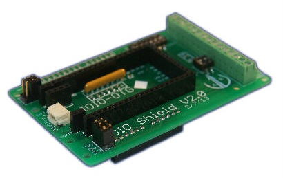
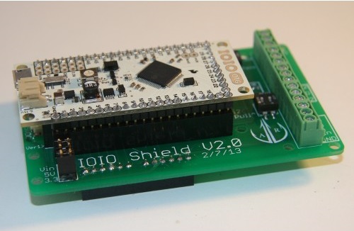
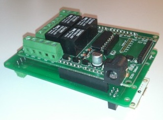
Plug your IOIO into one side, and Arduino Style Shield into the other, and start coding. It's a hard connection that doesn't leave any question whether or not there's any loose wires. Troubleshooting is as easy as swapping out components. The board scales levels when needed, provides power busses, and routes i2c between boards.
===For the most up to date information, visit the product's wiki: IOIO Shield Adapter.===
Features
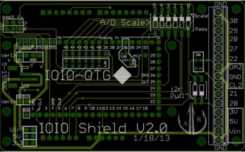
PIN MAPPING
Lots of time and energy went into developing the pin mapping between the Arduino side and the IOIO side to best make use of the IOIO's numerous pins. You can check out the pin mapping on the project's wiki. To the best of our, I matched function to function across the two boards.
A/D CHANNELS
The Arduino has 5v A/D converters, while the IOIO has 3.3V converters. To deal with this, we included a scaling circuit that scales all of the A/D pins down to 3.3V. There's also a bank of DIP switches that cutout this feature if you don't need it.
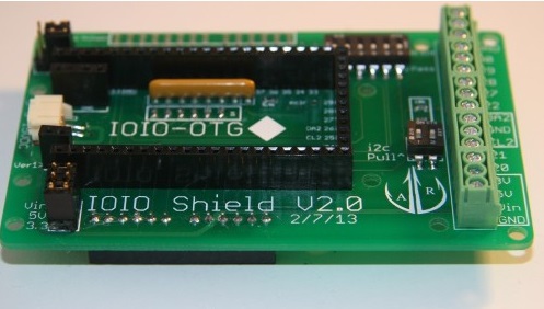
SCREW TERMINALS
A row of screw terminals allows you to easily and securely connect wires to the board.
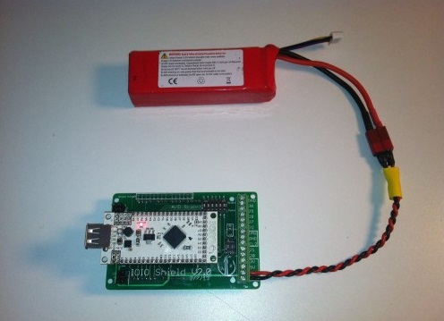
POWER
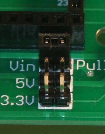
You can couple voltage to the shield selectively. Using jumpers, you can couple Vin, 5V, and 3.3V depending on what you need. Vin is also routed through a scale and limiting circuit to measure input voltage.
I2C BUSSES
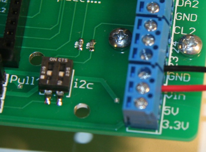
i2c busses are routed to the appropriate pins on the Arduino side, but are selectable due to the multi-function nature of the Arduino A/D pins. Also, the i2c bus that goes to the screw terminals has optional pull-up resistors. If you need them, just flip the DIP switches.